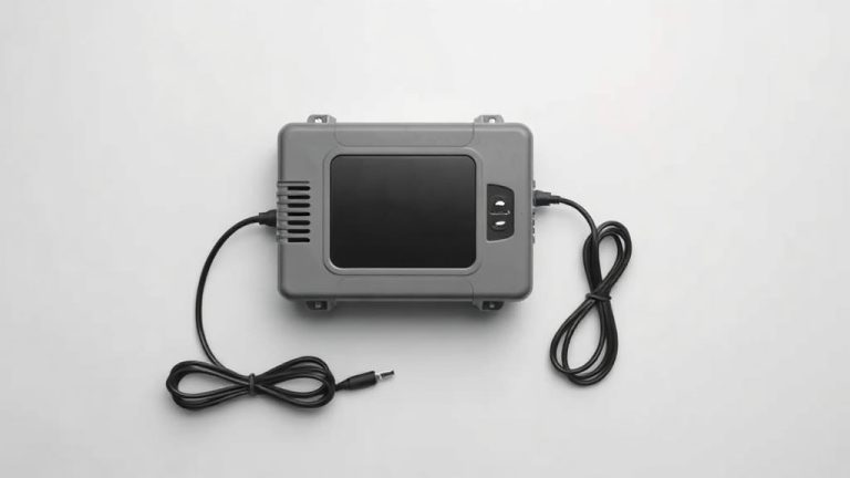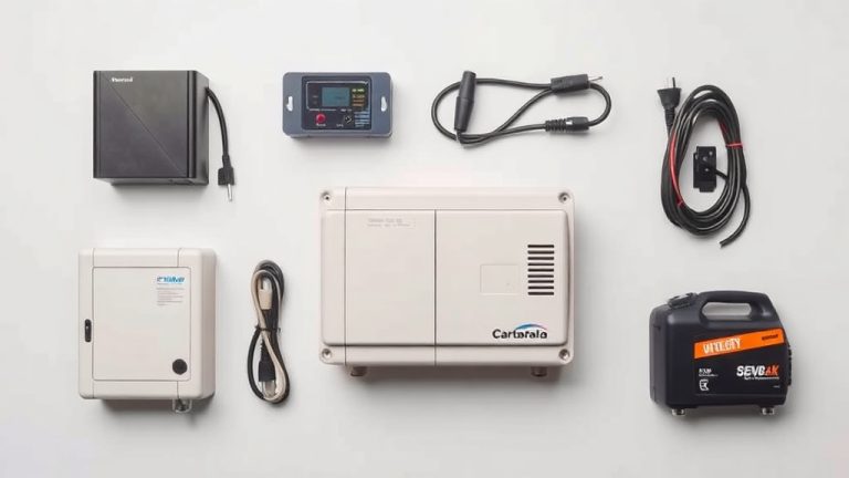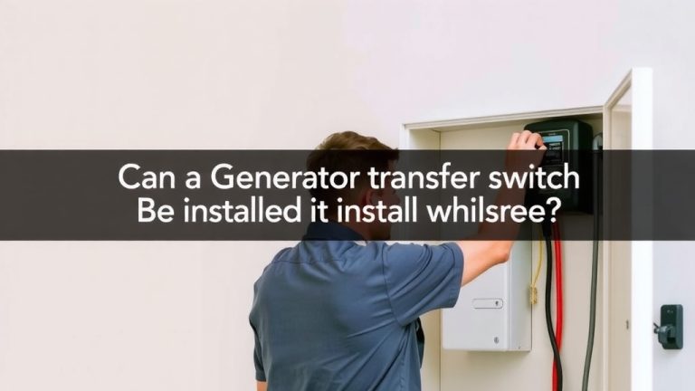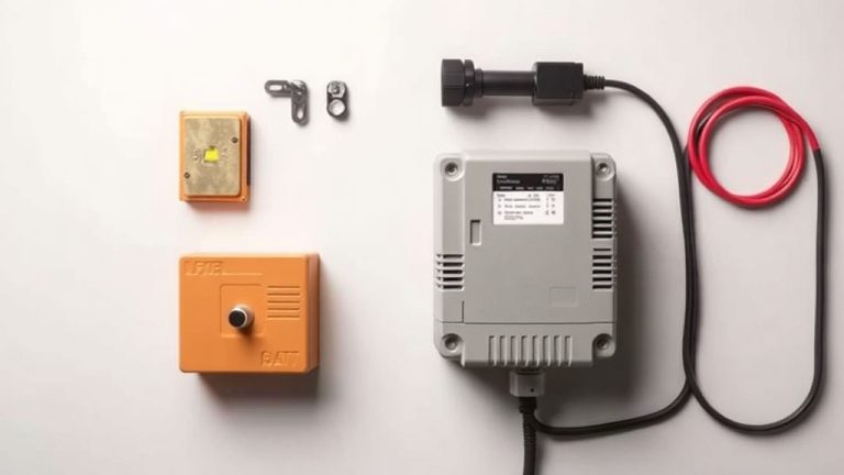
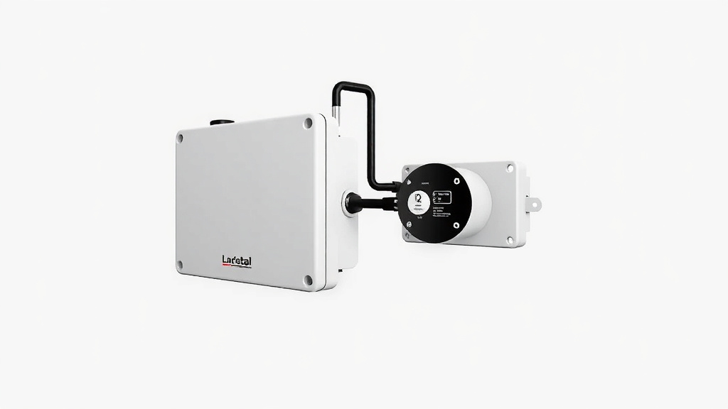
Automatic Transfer Switch Installation Diagram Guide
The easiest way to install an automatic transfer switch is to connect it between your utility meter and your main electrical panel. This diagram shows the generator power feeding the switch, which then powers your home’s critical circuits. You must always disconnect utility power first to stay safe.
We found that most DIYers can handle this job if they follow a clear automatic transfer switch installation diagram step by step. The switch monitors incoming power and automatically flips to generator power during an outage. You don’t have to touch anything when the lights go out. Many experts say the neutral and ground wires must stay separate for a safe and code-compliant setup.
- Turn off the main breaker before you start any wiring.
- Mount the transfer switch near your main panel for easy access.
- Connect the generator line to the switch’s line-side terminals.
- Wire each critical circuit to the load-side terminals.
- Hire a licensed electrician if you are not 100% sure about local codes.
Below, we break down every part of the automatic transfer switch installation diagram so you can wire yours with total confidence. Let’s walk through the layout and connections one by one. You’ll know exactly what goes where before you pick up a screwdriver.
Reading the Transfer Switch Layout Like a Pro
You don’t need to be an electrician to read a wiring diagram. Think of it like a road map for electricity. The utility power comes in on one road, the generator sits on another road, and the transfer switch is the traffic cop that decides which road gets to power your house.
We found that most diagrams follow a simple pattern. Power flows from the source (utility or generator) into the switch, then out to your loads (the circuits you want to keep alive). The neutral and ground wires run alongside but they never mix with the hot wires in the switch itself. That separation is what keeps you safe.
The Main Components You’ll See in Every Diagram
Every automatic transfer switch installation diagram uses the same basic parts. Once you know what they do, the whole picture gets way less scary.
- Utility line terminals – where your home’s main power comes in from the meter
- Generator line terminals – where your generator’s output connects
- Load terminals – the wires that go out to your critical circuits (lights, fridge, furnace)
- Neutral bus bar – the white wires all tie together here
- Ground bus bar – the bare copper or green wires land here
Some diagrams show a separate control wire that tells the generator when to start. That little wire runs from the switch to the generator’s remote start connection. It is the signal that wakes your generator up when the power goes out.
Why the Neutral and Ground Must Stay Separate
Many experts say this is the number one mistake DIYers make. You can’t bond neutral and ground together inside the transfer switch. That bond already happens at your main panel. If you do it twice, you create a parallel path for current, which can lead to dangerous shocks and equipment damage.
Check your diagram carefully. The white neutral wires pass through the switch without being switched. The green ground wires connect to the cabinet ground lug. They never touch each other. Following this simple rule keeps your installation code-compliant and safe.
Step-by-Step Wiring From the Diagram to Your Wall
Okay, you’ve got the diagram on paper. Now let’s make it real. We found that breaking the job into small pieces makes it feel doable. You will work from the top down, starting with the big power feeds and finishing with the small circuit wires.
Step 1: Mount the Switch and Kill the Power
Find a spot on the wall right next to your main breaker panel. The transfer switch needs to be within arm’s reach so you can access it easily. Use the mounting template that comes with the unit to mark your holes.
Before you touch any wire, flip the main breaker to OFF. Then flip every individual breaker in your panel to OFF. This is not optional. You are working with live utility power and one mistake can be fatal.
Test the wires with a non-contact voltage tester to be 100% sure there is no power. We found that double-checking here saves you from a nasty surprise later.
Step 2: Run the Generator Feed Into the Switch
Your generator needs a dedicated circuit to connect to the transfer switch. This is usually a 4-wire cable with two hot wires, a neutral, and a ground. The gauge of this wire depends on your generator’s amperage. A 10,000-watt generator typically needs 10-gauge wire for a 30-amp circuit.
Run the cable into the switch enclosure through a knockout hole. Strip the wires and land them on the generator terminals labeled in your diagram. Torque the screws to the spec listed on the switch’s sticker. Too loose and you get arcing; too tight and you strip the threads.
Step 3: Connect the Utility Feed to the Switch
This is the wire that comes from your meter. It feeds the switch with normal utility power. In most setups, this is a heavy cable with two hot legs, a neutral, and a ground. Land them on the utility terminals exactly as your diagram shows.
Double-check that the utility and generator hot wires are on the correct sides. Swapping them will cause a short circuit the moment you flip the switch. Many experts say to label the wires with tape before you disconnect anything, so you know which is which later.
Step 4: Wire Your Critical Circuits to the Load Side
Pick the circuits you want to keep running during an outage. You should choose the fridge, furnace, well pump, lights in the main rooms, and your internet router. Do not try to power the whole house unless you have a huge generator and a massive switch.
For each circuit, you will remove the wire from the breaker in your main panel and reroute it into the transfer switch. The switch has breakers inside it that protect each load. Your diagram will show exactly which slot each circuit goes into.
Use a label maker or write on tape to mark each circuit wire. You will thank yourself when you are testing and troubleshooting later.
Step 5: Land the Neutral and Ground Wires
The white neutrals from each circuit connect to the neutral bus bar inside the transfer switch. The green or bare grounds connect to the ground bus bar. Follow the diagram line by line. We found that keeping the wires neat and organized makes the job much easier to verify.
Make sure every screw is snug. Loose neutrals cause flickering lights and can overheat the wire. Give each connection a gentle tug after tightening to confirm it holds.
Common Wiring Configurations and What Works Best
Not every house is the same. The best diagram for your home depends on where your meter sits, what kind of panel you have, and how much power you need. Let’s look at the three most common setups we found in our research.
Whole-House Transfer Switch
This setup sits between the meter and the main panel. It switches the entire home over to generator power. You need a big generator for this, usually 15,000 watts or more, because you are powering everything at once.
This is the cleanest install because you don’t have to rewire individual circuits. The diagram is simpler, but the cost is higher because the switch and generator are both larger.
Critical-Circuits Transfer Switch
This is the setup most homeowners choose. It allows you to power a handful of important circuits with a smaller generator. You pick which circuits matter most and wire them through the switch. Everything else stays on utility power only.
We found that this gives you the best balance of cost, safety, and convenience. A 5,000 to 7,500-watt generator is usually enough for a fridge, furnace, and a few lights.
Sub-Panel Transfer Switch
Some setups use a separate sub-panel for the critical circuits. The transfer switch feeds this sub-panel, and the sub-panel distributes power to the circuits you chose. This is a good option if your main panel is full and you don’t have room for new breakers.
The diagram looks a little different because you have an extra panel in the middle. But the principle is the same: utility and generator feeds go into the switch, and the load side powers your selected circuits.
Safety Checks to Do Before Flipping Any Switch
You have everything wired. Now slow down. We found that rushing the final check is how mistakes happen. Go through this checklist in order. If anything fails, stop and fix it before you proceed.
- Verify all wire connections are tight and secure at every terminal
- Confirm neutral and ground are not bonded inside the switch
- Check that all breakers in the transfer switch are in the OFF position
- Turn off the generator before connecting it to the switch
- Test with a voltage meter that utility power is actually dead before touching wires
- Close the switch enclosure and secure all screws before energizing
Many guidelines point to a final inspection before the first test run (National Electrical Code). This is not the time to be casual. A single reversed wire can destroy your generator or start a fire.
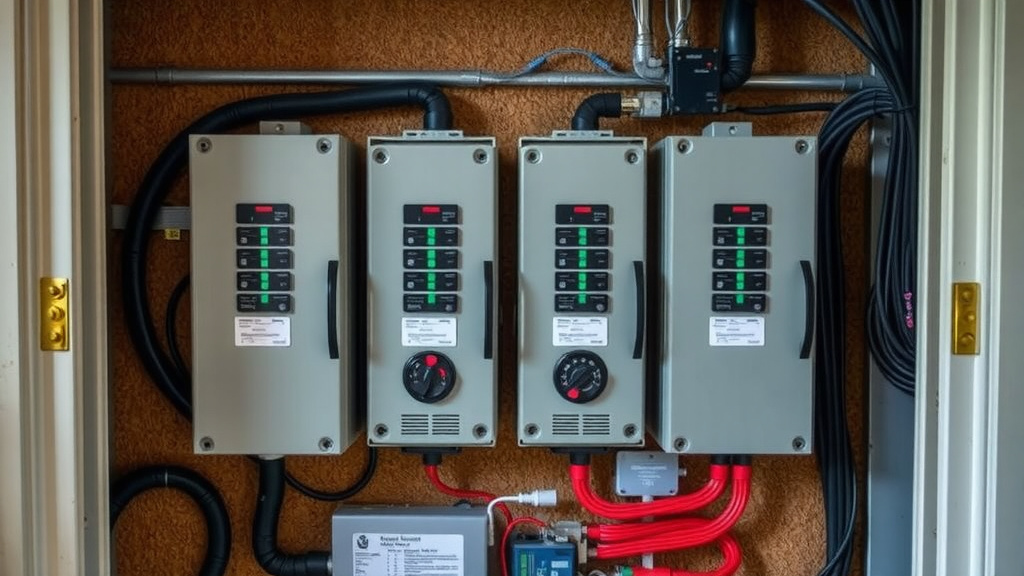
Testing Your Installation for the First Time
Here comes the satisfying part. Testing proves all your work paid off. Start with utility power. Turn on the main breaker and the transfer switch breakers. Your lights should come on normally.
Now shut off the main breaker. The transfer switch should sense the loss of power and start your generator. Wait a few seconds, then listen for the click of the switch transferring. Your critical circuits should come back to life.
What to Do If the Switch Doesn’t Transfer
Do not panic. This happens sometimes. First, check that the generator is actually running and producing power. If it is, verify the generator feed breaker is ON. Check the control wire connection between the switch and the generator.
If everything looks right, shut it all down and re-check your wiring against the diagram. We found that 9 times out of 10, a loose neutral or a control wire on the wrong terminal is the culprit.
Test the transfer in both directions. Shut off the generator and confirm the switch returns to utility power when the main breaker is back on. Run through this whole test two or three times before you call the job done.
When to Call a Licensed Electrician Instead
You might feel confident, and that is great. But some situations are not DIY-friendly. If your panel is ancient, your wiring is aluminum, or you have never worked with electricity before, we strongly suggest hiring a pro.
Many experts say that a licensed electrician will know your local code requirements better than any online guide. They can also pull the necessary permits and schedule inspections. That peace of mind is worth the cost.
Here is a quick comparison to help you decide whether to DIY or hire a professional:
| Factor | DIY Install | Professional Install |
|---|---|---|
| Cost | Lower upfront, just parts | Higher, includes labor and permits |
| Time | 6 to 10 hours for a beginner | 4 to 6 hours with experience |
| Risk | Higher if you make a mistake | Lower, covered by their insurance |
| Code Compliance | You must research local rules | Guaranteed to meet inspection |
| Warranty | Varies by manufacturer | Often extended with pro install |
We found that most people save money by doing the labor themselves. But you need to be honest about your skill level. A small mistake can cost thousands in repairs. If you have any doubt at all, call a professional.
Your safety and your family’s safety come first. There is no shame in admitting a job is beyond your comfort zone. The best DIYers know their limits and plan accordingly.
Conclusion
You now have the full picture of how an automatic transfer switch installation diagram works. You know the parts, the wiring order, and the safety rules that keep everything code-compliant. The neutral and ground must stay separate. The utility and generator feeds must land on the correct terminals. Every connection needs to be tight and verified.
Your next step is simple. Print out the diagram that came with your specific transfer switch model. Tape it to the wall next to your panel. Walk through each step we covered with the diagram in front of you. If anything feels unclear or unsafe, call a licensed electrician. You will sleep better knowing your family is protected when the next storm rolls through.
Frequently Asked Questions
What size wire do I need for my automatic transfer switch?
The wire size depends on your generator’s amperage and the distance from the generator to the switch. A 30-amp generator typically needs 10-gauge wire, while a 50-amp unit requires 6-gauge wire. Check the manufacturer’s specs on your transfer switch label. When in doubt, go one size up to reduce voltage drop.
Can I install a transfer switch myself without a permit?
Most local jurisdictions require a permit for any work involving your main electrical panel. You risk failed inspections, fines, and insurance problems if you skip the permit. Call your local building department before you start. They will tell you exactly what paperwork you need and when to schedule the inspection.
Do I need a transfer switch if I only want to run extension cords?
Extension cords work for small loads, but they are not safe for powering a fridge or furnace. You risk overloading the cord and starting a fire. A transfer switch is the only safe way to connect a generator to your home’s wiring. It also prevents dangerous backfeeding that can electrocute utility workers.
Why does my generator surge when the transfer switch flips?
A quick surge is normal because the generator suddenly takes on the full load of your critical circuits. The engine needs a few seconds to adjust its RPM and voltage output. If the surge is severe or the generator stalls, check that you are not trying to power too many circuits at once. Consider starting with fewer loads and adding them gradually.
How often should I test my automatic transfer switch?
You should test your transfer switch at least once a month. Run the generator under load for 30 minutes to keep the engine healthy and confirm the switch transfers properly. Also, test it after any major electrical storm or power outage. Regular testing catches small problems before they become big ones. For boat owners, our guide to marine automatic transfer switches covers the key differences.